
By Josh Cosford, Contributing Editor
Seals are often an afterthought when it comes to designing fluid power systems, which makes sense for the majority of applications where off-the-shelf is good enough. Designers select pumps, valves, and actuators based on criteria like flow rates, valve configurations, and pressure capacities, but most of those primary components are ordered with their standard seal packages. It does make sense for manufacturers to offer seals that suit 90% of fluid, temperature, efficiency, and service-life conditions on the market, but what happens in the other 10% of outliers is important to know.
A seal’s primary function in fluid power is to contain fluid molecules under pressure to facilitate the transfer of energy from the hydraulic pump or air compressor to the actuators. Although facilitating pressure differential is the seal’s modus operandi, they’re usually required when different media are to be kept separate, such as oil and glycol or water and air. In like manner, and true to a seal’s primary function, sometimes seals will save a fluid from itself, such as shaft seals on submerged hydraulic pumps, where potentially dirty reservoir oil must be kept from the pristine internals of your pump.
Since a seal’s primary functions are pressure containment, fluid separation, and contamination control, they are also required for lubrication. Many examples of pumps, motors, valves, and cylinders use oil or grease for lubrication, and seals ensure said lubricants remain as intended within bearings, rods, and spools to prevent excessive wear while sometimes working double duty with one of the above functions.
Seal types and their functions
Because incorrect seal types and materials are among the most common root causes of failures, it can go very wrong, very quickly if you don’t take the foresight to replace “standard” seals with more suitable ones. Let’s start by looking at the seal’s functions more closely so you can apply this knowledge to future applications.
Fluid containment sounds easy, especially because we’ve refined the technology so well and take it for granted. But keeping air and oil from spewing out from cylinders, valves, manifolds, pumps, and motors takes more than simply slapping an O-ring in a pocket. Seals often differ in construction and material based on static or dynamic needs and must withstand the shear forces created when modest to extreme pressure attempts to liquify the seal and extrude it through precise gaps between structures.
Seals are categorized as either static or dynamic, meaning that they either simply contain pressure to seal the space between two stationary components, or that they must also contain that pressure between two pieces that are either rotating or reciprocating.
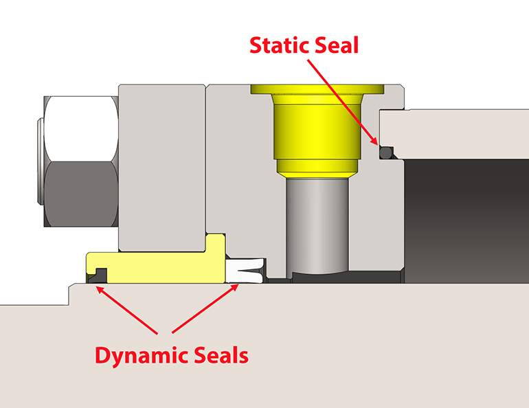
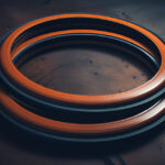
Static seals (Figure 1) are installed in and on pump covers, cylinder barrels, cartridge and stack valves, and anywhere they prevent the passage of often-pressurized fluid through the gaps of two or more connected components. Here you can see that a simple O-ring seals the barrel groove and the barrel on this hydraulic cylinder. Without this seal, or when it is damaged, fluid simply leaks out of the gap, reducing pressure, flow, or both, while making a slippery mess in hydraulic applications. The visual also helps explain why NFPA-style hydraulic cylinders use significantly larger tie rods, which prevent stretch and the resulting opening of the extrusion gap under high pressure.
The most common static seal is the simple O-ring, as shown in Figure 1, which fits nicely into square, machined pockets. They’re inexpensive, widely available, and are manufactured from a variety of polymers suitable for every application (more on that later). Most static seals will deform to take the shape of their cavities, which is a design feature that ensures gaps are fully sealed and leak free. Should such deformation become extreme under high-pressure hydraulic applications, soft seals can extrude through even the tiniest gaps, so install plastic backup washers where gaps cannot be minimized.
Backup washers are thin, hard plastic discs that sit on one or both sides of an O-ring to buttress it against the pressure trying to squeeze the soft rubber through the opposing gap like so much Play-Doh. The backup is hard enough to remain rigid despite the pressure acting on it and protects the O-ring from pressure-spike-induced extrusion. Some manufacturers offer specialty-designed static seals for high-end applications, but my experience tells me that O-rings are satisfactory for the majority of static seal applications, and an inexpensive backup washer is the only heavy-duty addition required.
Dynamic seals (also Figure 1) still guard the passage of liquid and air through the small gaps but do so between stationary and moving parts, such as piston rods, pump/motor shafts, and valve spools. There wouldn’t be much “power” in fluid power unless something moved with force to push, pull, and turn, so the “machine end” of cylinders and motors needs to move independently of the mounted portion. Seals are now expected to slide across their respective shafts without excessive friction, yet with sufficient strength to prevent extrusion. You can see here that the rod lip seal facing right prevents the escape of precious air or oil molecules, while the wiper seal on the left discourages the ingestion of externally sourced contamination.
The double-duty that dynamic seals must perform is actually quite extreme; they must offer the same pressure-resisting capacity as static seals while also combating damage and wear from friction. Poorly designed and constructed dynamic seals can roll or pinch catastrophically, while inappropriately selected seals can either wear rapidly or leak prematurely.
Consider velocity in selection
Oftentimes, you must balance pressure capacity with velocity, because high-pressure seals are either interference-fit (their uninstalled dimensions are larger than the pocket they’re installed in) or they are U-cup or lip-style seals that use the fluid pressure to push the lips outward toward the sealing surface with more vigour as pressure rises. As you would expect, rubber pushing hard and dragging on a polished, chromed shaft will exhibit high friction, which itself generates heat, thermal breakdown, and rapid wear.
Seal design and material combinations are subject to a velocity cap that manufacturers recommend designers adhere to. Modern seal designs and materials are getting better at offering the best of both high-pressure capacity and high-speed operation, but, in general, seals come in low-speed, medium-speed, and high-speed configurations of approximately 1.5 ft/sec, 3 ft/sec, and 6-12 ft/sec, respectively. High-speed seals may inherently allow more fluid leakage as a consequence of lower friction, but the above numbers generally apply to polymer seals only.
For ultra-high-velocity applications, you must do away with polymer seals altogether and accept that you’re trading acceleration and speed for higher leakages, which means using only guide strips or cast-iron rings that offer reduced sealing but also reduced friction. Such combinations are the best choice for high-heat and high-pressure working conditions, since cast iron offers nearly unlimited heat and pressure resistance. Often, these are used with high-flow circuits featuring sophisticated controls that can compensate for leakage, but expect to use these designs if you require 15 feet per second or more.
Selecting the right profile
Where it gets confusing for fluid power designers is the selection process when looking for the right seal profile. The profile is the design as it appears from its cross-section, which partially dictates the performance criteria discussed thus far. You can select from U-cups, O-rings, buffer seals, vee packings, T-seals, compound assemblies, wipers, quad rings, and many other styles.
The below chart (Figure 2) shows many of the popular seal profiles, common applications, and expected maximum velocity. I’ve included dynamic (D) and static (S) pressure ratings and temperature in the chart, but these data are not gospel, so use them only as a starting point. The reality is that there are as many seal combinations as there are designers.
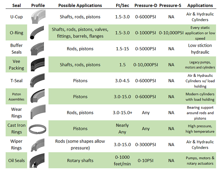
Still, the chart is not comprehensive, so I’ll discuss a few important notes. Remember that U-cups and lip seals are pressure energized — they may leak at very low pressure, especially with a fitment that is low-interference, but they offer low to moderate friction. Also, remember that U-cups are directional, and two are required for double-acting applications, with their cups facing toward the pressure.
T-seals can be high- or medium-friction depending on their material, but are generally great for reliable, high-pressure capacity, despite what some consider an old technology. They can be costly, however, since they come in three pieces. Vee packings (chevron seals) are the oldest technology still in use today, but are bulky, have inconsistent friction, and are maintenance-intensive. Their primary advantage is their adjustable preload, as you can add “vees” to the packing stack and adjust their preload.
Wipers are used primarily on the external side of the piston rod, where they are designed to remove any foreign material, such as dust, melted plastic, or mud from the rod as it retracts. Some manufacturers offer a combination seal/wiper that adds an extra layer of rod sealing should the primary rod seal fail. For extra-demanding applications, such as a welding robot, metal scrapers can replace wipers, which can even remove molten metal during retraction.
Not all seals are for linear applications, of course, as rotating shafts need sealing as well. Although many pneumatic motors work well with simple O-rings, heavy-duty air motors and some rotary actuators use the U-Cup-shaped rotary seal. These employ a metal support ring that provides excellent sealing even at atmospheric pressure because that ring holds it in place, rather than pressure or interference fit. On the internal diameter that rests against the shaft, an “energizer” made from a tiny coil spring or just some rubber will hold the seal against the shaft, even as it wears.
Material matters
The material of the chosen seal plays a leading role in all the factors of performance — pressure capacity, temperature, and velocity. We don’t need to get into the history of polymers, because we’ve gone through a lot of poor natural and synthetic materials before we got to today’s superior options.
(Poly)Urethane and Buna-Nitrile are, by far, the most common choices for air and hydraulic applications. Both options are inexpensive, readily available, and work over a wide range of pressures and temperatures. Their polymers are ideal for air and oil and come in various shapes and sizes for the majority of valves, cylinders, and motors.
Most pneumatic valves, cylinders, manifolds, and FRLs will use Buna-N. It offers great sealability, fair velocity, and suitable temperature range. In short, it’s nearly perfect for pneumatics. They’re inexpensive, readily available, and, when it comes to O-rings, offered in industry-standard sizes and thicknesses. High-speed pneumatic actuators may require inline lubrication, however, because most Buna-N seals are not designed for the crazy speeds pneumatics can reach.
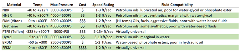
Buna-Nitrile finds its way into many hydraulic applications, as well, especially in static locations. Flanges, manifolds, fittings, covers, and everywhere two stationary parts are joined can be done with this synthetic rubber. There are limitations on fluid and temperature compatibility, of course, as these are not suitable for exotic ester fluids or temperature extremes, but they are probably suitable for over 90% of your static needs.
Urethanes have taken over the hydraulic seal market, especially with modern polymers offering previously impossible temperature and fluid compatibility combinations. They make fantastic dynamic seals for shafts, rods, and pistons, and will provide high-pressure protection for even the most demanding applications. Although the majority of urethane seals are not compatible with water-based fluids, a few manufacturers have new technologies that works with HWBF and water-glycols.
When the fluid or temperature is extreme, the venerable choice is a fluorocarbon polymer, typically referred to as Viton. Viton is perfect for high-heat applications, such as steel mills, and also where exotic and aggressive fluids are used. Note, however, that Viton is a soft rubber, and care should be taken when selecting it for high pressure.
Speaking of high pressure — this is where plastics come in. PTFE (Teflon) and nylon are used in applications where a durable and stable material is required, such as those with extreme pressure or wide temperature range. PTFE is immune to nearly all fluid types and is stable even in arctic conditions. However, its hardness makes a poor seal, so it’s often used in conjunction with rubber energizers and expanders that push the seal against the seal surface.
Some of the less-popular materials are HNBR and EPDM, each of which has two entirely different downsides. EPDM is not compatible with oil, so it is generally used as an excellent choice for water-glycol systems. NHBR is a version of nitrile that is resistant to heat, oil, and abrasion, but is quite expensive. Gaining popularity is the thermoplastic elastomer, Hytrel, which is used in combination with some of the above polymers to performance and increase longevity.
Of course, manufacturers offer most of the above seals in various compounds of hardness, which is measured on the Shore scale. Most fluid power seals are on the Shore A scale, so that includes all the synthetics discussed above, except some plastic material, which might be ranked on the D scale. Most seals range from 70A to 90A in hardness.
A hardness of 70A is soft and conforms well to the pocket or space the seal is installed, even at low pressure. However, a 70A seal will have more friction and will wear faster. Meanwhile, going up to 80A or 90A results in a harder rubber that better resists deformation under high pressure while offering lower friction and a longer service life. Conversely, the harder material will more likely leak than a soft one, and is often much harder to install.
Installation and design tips
Finally, all fluid power designers must be aware of the installation requirements for each seal, as these can dramatically improve or degrade seal performance. The geometry and quality of the seal groove must be intelligently designed for every location a seal is installed. The tube end seal, the shaft hole of the pump housing, the pocket of the D03 valve interface, and literally every location where a seal is installed need to have the correct depth, width, chamfer, and surface finish.
The width and depth ensure the seal has just enough radial squeeze and axial clearance. A groove that is too shallow prevents proper interfacing, while one that is too large allows the seal to float in its cavity. The two interfacing surfaces must also combine to offer adequately small extrusion gaps, such as the distance between the piston OD and the tube of an air or hydraulic cylinder. Tiny clearances are difficult to manufacture and risk thermal-expansion issues, while excessive clearances provide an easy path for the seal to “nibble” out through during reciprocations.
Once you have the seal pocket finalized, you must consider the chamfer requirement around the groove. A chamfer will make the seal easier to install, in many cases, but care should be taken to avoid doing so across the sealing edge, where such a chamfer just provides an easy path for extrusion. When it comes to dynamic applications, ensure the sealing surfaces (such as the rod or barrel ID) have the appropriate surface finish. If the surface is too smooth, there is poor oil retention, while if the surface is rough, the seals wear rapidly.
It’s easy to look at seals and believe they’re just a bunch of rubber and plastic bits that stop leaks, but such views do no justice to the engineering and refinement that properly designed, selected and installed seals provide to the value of a pneumatic or hydraulic machine. Whether you’re designing a simple pancake cylinder or engineering a piston pump from scratch, all the above criteria are essential for the fluid power designer to consider.


Leave a Reply