
Advances in rod seal design, materials, and test methods help improve the efficiency and reliability of hydraulic systems.
Contributed by Chuck White, Director of Commercial Development, Hallite
Friction is one of the most common and underestimated causes of rod seal leakage in a hydraulic system. However, measuring and addressing it can be a challenge because it requires skillful balance. Too much friction will cause excessive seal wear, reduced seal life, and diminished hydraulic system efficiency, while too little or insufficient friction will result in excessive leakage. Left unchecked, both situations will lead to hydraulic system failure.
In today’s demanding operating environments, hydraulic cylinders work harder, faster, and for longer cycles than ever before. This has triggered an increased need for the most effective means to address friction-related rod seal inefficiencies in a hydraulic system. We will review some important developments that are enabling OEMs to overcome rod seal friction challenges. And since the U-cup is the most common type of rod seal profile used by the fluid power industry, it will be our focus.
Design
There are four major rod seal design factors that have a significant impact on friction — preload, groove fill, geometry, and materials.
Preload is the spring-force exerted on the sealing surface by the seal to prevent leakage. It defines the amount of squeeze a seal has in the assembly. Excessive preload provides better sealing with the downside of too much friction and wear. This eventually destroys the seal. When seals are subjected to pressure, they respond by creating more load on the sealing lips to contain fluids at increased pressure. Pressure causes a seal to deform, resulting in additional contact of the sealing lips to the rod, so in low- to medium-pressure environments of 1,000 to 3,000 psi gradual deformation occurs. However, in a high-pressure environment of 10,000 psi deformation will cause full seal-to-rod contact and higher friction.
Most of the U-cup seals available today are considered dynamic, meaning they respond to various pressures and adjust preload to maximize seal life. It is critically important to understand and properly calculate the amount of preload needed at certain pressures when designing rod seals for specific applications. Also, give proper attention to preload boundary lubrication — the light film of oil essential to preventing seals from wearing out due to friction and heat.
Groove fill ensures proper seal position in the application. Insufficient groove fill leads to seal rocking and improper seal position which causes leakage. Groove overfill leads to excessive seal wear, extrusion, and increased potential for leakage. Extrusion gap is the space left between the rod and the mating hardware. When a seal is subjected to high pressure, materials will tend to push through this gap (or extrude) and contribute to seal failure. A back-up ring is often used to help prevent extrusion in high-pressure applications. Attention in this regard is extremely important because improper extrusion gap is a key contributor to premature rod seal failure.
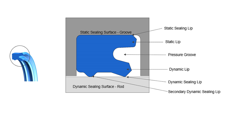
Geometry depends on the application. There are a variety of symmetrical and asymmetrical rod seal U-cup geometries available. Factors to consider when selecting the right option include friction (or stick-slip) during operation, pressure range, acceptable leakage, and the type of rod wiper. An advantage of the symmetrical geometry is that it can be used interchangeably as a rod or piston seal, but it offers less stability in the groove than the asymmetrical seal when under load, creating a hinging effect. The symmetrical seal also presents more friction. An energizer can be used to create preload.
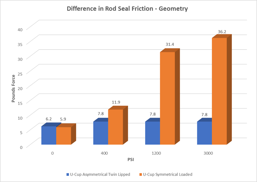
The asymmetrical geometry must be designed as either a rod or piston seal. Its profile allows more fluid flow into the pressure groove than the symmetrical seal, making it more responsive with improved stability in the groove under load. The twin lip asymmetrical design provides additional stability and sealing. This option tends to present less friction.
Single and twin lip asymmetrical U-cup rod seal geometries offer a range of characteristics and advantages. The single lip U-cup rod seal is a low-friction seal with limited sealing capabilities when used without a wiper, so a wiper is recommended to assist with protecting the cylinder from harmful contaminants. In terms of pressure, the single lip U-cup rod seal performs better than its twin lip counterpart, but it is not ideal for high-pressure applications. Pressure spiking will cause the single lip U-cup seal to split down the middle of the pressure groove. For example, in a backhoe operation with pressure spikes upwards to 10,000 psi, the single lip U-cup is not appropriate because it is limited to a maximum rating to 6,000 psi.
The twin lip U-cup rod seal is a high-pressure seal rated to 10,000 psi. It employs a primary and secondary sealing lip, offering improved sealability when compared to the single lip design. It presents more friction than the single lip U-cup rod seal but offers better performance under pressure. This is because stress is diverted to the secondary lip instead of the pressure groove, enabling the seal to better withstand pressure spikes. A shock-absorbing energizer with a back-up ring prevents extrusion.
Materials play an important role in managing rod seal friction. The most commonly-used materials in U-cup rod seal design are elastomers (NBR, HNBR, FKM), Polytetrafluoroethylene (PTFE), Polyurethane (TPU), and Polyester (TPE). Softer materials tend to stick to dynamic surfaces and offer better sealability, while harder materials offer less friction but also less sealing. The material’s interaction with fluid, or fluid compatibility is also important especially as the industry focuses on the use of more environmentally-friendly oils. Abrasion and compression set resistance should also be taken into consideration when designing rod seals. Remember that no single material is appropriate for every situation, so understanding the application is essential to material selection.
Fluid viscosity and surface finish
Fluid viscosity and surface finish are two additional and very important factors that impact U-cup rod seal friction. Using improper viscosity fluids can starve the seal of essential lubrication, resulting in excessive wear. This was the case with a customer that reported a noisy cylinder accompanied with jittering of the rod on extend and retract. The customer was using low-temperature ISO 15 oil for an ambient temperature application. After the fluid was changed to an ISO 32 oil type, the problem was addressed; however, the life of the rod seal was greatly reduced while the ISO 15 oil was in use. This required a cylinder rebuild before expected end of life.
Another customer requested testing to show startup performance of rod seals at extremely cold temperatures. The test employed a customer-recommended ISO 15 Arctic Hydraulic Fluid with a pour rating of –70°F with favorable results, but the oil congealed at –60°F resulting in very little boundary lubrication. Although the seals performed well at low temperatures, extended operation without a rise in oil temperature meant the loss of seal performance over time. These are just two examples highlighting the role and impact of fluid viscosity on rod seal friction.
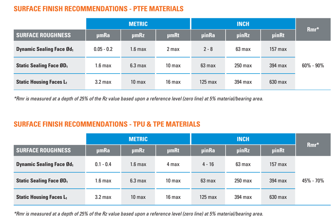
Surface finish is a measure of the lay, surface roughness, and waviness of a surface. Measured using Ra, Rz, RT, and Rmr, surface finish is critical when attempting to minimize rod seal friction and wear. It must conform to recommendations as defined for the seal profile and material being used. RT and Ra are the most common surface finish measurement types.
Understanding rod seal leakage
It’s a fact. All seals leak. So exactly how much leakage is acceptable, and how is it measured? Unfortunately, a standard measurement for leakage does not exist. Tolerance for rod seal leakage in each cylinder application is based solely upon the operator’s sensitivity within the environment in question. Generally, the quantity of leakage is assessed visually. For example, the amount of tolerable rod seal leakage in a hydraulic cylinder used within an agricultural production environment will differ greatly from what is allowable in a food and beverage processing environment.
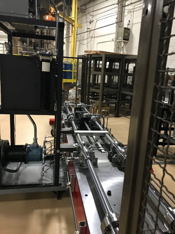
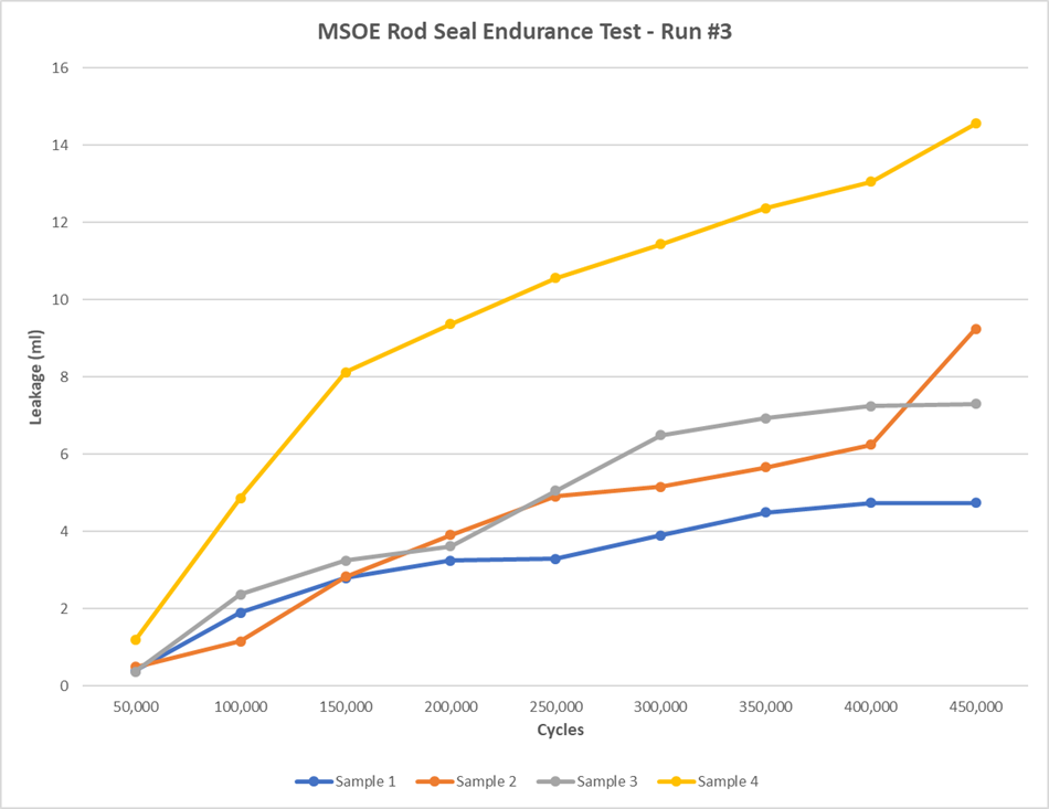
To better determine which rod seal design offers optimum performance for a specific application, Hallite partnered with MSOE to develop a rod seal endurance rig that tests 16 different rod seals simultaneously.
Testing is conducted under a variety of operating conditions using a range of fluids. Performance characteristics such as stroke speed and length, pressure and temperature, and pressure differential (extend and retract) are included in the test.
A major component of the test rig is physical leakage measurement which is taken every 50,000 cycles (ml). Leakage between the rod seal and wiper and the outboard of the wiper is evaluated, and data collected enables calculation and evaluation of leakage across the tested seals. This approach also provides a visual record of how the seals react to specific surface finish changes.
Conclusion
Assessing and managing rod seal friction can be challenging, but it is not impossible. Sealing solutions should be designed with the primary factors that impact friction in mind:
- Preload boundary lubrication
- Groove fill
- Geometry
- Material
Since no hydraulic cylinder application is leak-free, determine how much leakage is acceptable, and then plan operations that function within a defined set of parameters.
Hallite
hallite.com/us/


Leave a Reply