By Josh Cosford, Contributing Editor
When it comes to hydraulic system design, filters are often overlooked and given the back seat to pumps, valves, and actuators. Such logic ignores the importance of filters in the performance, precision, and reliability of hydraulic systems, and such considerations start with the design of the hydraulic package itself.
Your hydraulic machine design starts with an understanding of functional requirements, such as “how much to lift and how far?” Then you proceed to the details of control, such as “how fast and how precise?” Finally, ask yourself, “How reliable and easy to maintain?” This last part of the equation is where the hydraulic designer must spend time to ensure customers receive a reliable Toyota, not a top fuel dragster, in terms of reliability.
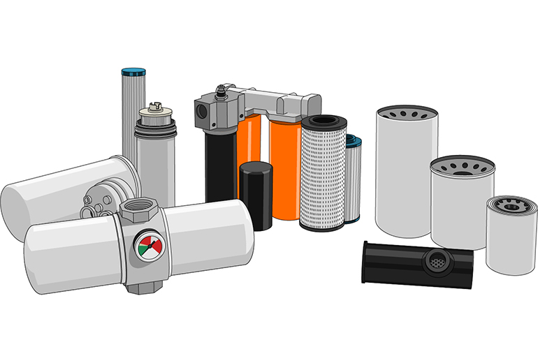
You must consider three filter criteria when designing your hydraulic system: location, size, and efficiency. Location will also dictate the construction type of your filter, and size will play a role in both flow and capacity, while efficiency determines how effectively particles are trapped.
It’s all about location
There are various locations where you should install a filter; some are optional, and others (controversially) are not recommended, such as suction filters. Once you have your hydraulic schematic complete, which is an early step in the process, you can consider the common recommendations for where to install them.
Almost all hydraulic systems have some form of return line filter, and if there is only one, it tends to reside in this location. In most cases, the return line, with exceptions such as pump case drain lines, terminates system flow at the reservoir. You can expect the entire pump’s output to flow back through the return line filter, ensuring the majority of the fluid exiting the reservoir returns to it cleaned.
Return line filters also offer the greatest variety in construction type and the most options for off-the-shelf element replacement. The construction type often follows the industry in which the hydraulic machine operates, ranging from mobile off-highway equipment to ultra-precise injection molding machines. Sometimes a given industry inherits a customer base with a preference for legacy machinery, and those preferences must be respected.
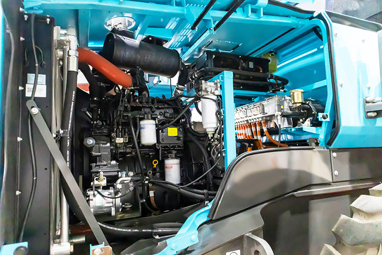
Tractors and AG equipment, for example, nearly exclusively use the venerable spin-on filter assembly for their hydraulics (Figure 1). Their appearance is similar to spin-on engine oil filters, which use a deep-drawn metal can as the housing. During manufacturing, the filter material is inserted into the canister before the thread plate is installed, and then the can lip is rolled to secure the plate. They are inexpensive and rapid to manufacture, especially given economies of scale in the automotive-style plants that produce them.
Like other return line filters, the spin-on filter element has limited pressure capacity, so don’t expect anything above 250 psi in most cases. They’re popular because they’re proven technology in an economical package, based on billions of canister-style filters used on internal combustion engines. From the designer’s perspective, select them when the budget allows, and when you need to mount them away from the reservoir or at another remote location. Their filter heads are equipped with tapped holes to facilitate mounting brackets, but you’re also welcome to mount them rigidly using the plumbing adapters.
Inline filters are mounted similarly to spin-on assemblies, using either bracketry or plumbing, but are often a rung higher on the quality ladder, both in terms of pressure rating and filtration efficiency. With a few exceptions, spin-on elements are offered with paper or cellulose media, although some premium brands offer media with an “absolute” rating (more on that later). Meanwhile, you can expect the aluminum or steel inline filters to be offered with the best filter technology while enjoying two or three times the pressure rating.
Although described as inline filters, this series is still mostly used for either return lines or kidney loops, which are dedicated filter circuits that use a low-flow pump to circulate tank oil continuously to keep it clean. Because pressure and work lines often require 2,000-5,000 psi capacity, the aluminum construction of inline filters is often considered “medium-duty” and limited to 500-1,000 psi.
My personal favorite return filter setup offers the best combination of filter efficiency, space-saving design, and cleanest element replacement technique — the in-tank return filter. These flanged units are mounted in a templated cutout in the reservoir, with only their heads and covers exposed. The assembly sits mostly below the oil level, and there is no “bowl” where oil must be caught during filter element replacement. The removable lid (either twist-off or screwed-flange) allows the dripping element to be removed from the top, preventing big messes while speeding up replacement.
The return filter also offers the widest variety of options, making it a solid pick for your hydraulic machine. They can include incorporated breather vents, multiple inlet ports, a variety of bypass indicator technologies, and the largest variation of filter media quality. Manufacturers will also offer their widest range of filter media options for in-tank assemblies: high-efficiency, wire mesh, water-absorbing, and other proprietary options, such as recyclable or economy choices.
The final, and most demanding, filter location is smack dab in the middle of a pressure line, either after the pump or before a delicate sub-circuit, such as a servo valve and precision actuator. Pressure filters help to isolate components or subsystems from unexpected contamination influx from some other location. Hydraulic pumps, for example, usually enjoy clean, filtered fluid because return filters catch the internally-generated debris from motors, valves, and cylinders. But should the pump itself decide to let go in dramatic fashion, it spreads its contamination to every downstream component before finally being trapped by the return filter. The post-pump pressure filter catches the bulk of the material, saving downstream components.
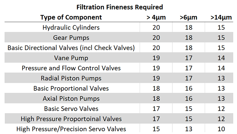
For examples such as high-response proportional and servo valves, the inline pressure filter provides an extra layer of ultra-fine protection specific to that subcircuit. Without getting deep into ISO 4406 cleanliness codes (which you can read here), the designer must be aware that servo valves require ultra-fine particle removal, such as can be had with 3-micron, ultra-high-efficiency filter media, despite the rest of the machine running happily with 10-micron elements.
Quality filters made from ductile iron and steel land on the pressure curve starting around 4,000 psi. You’d hate to see a nominally rated 3,000 psi filter bump head-on into its fatigue pressure due to a load-induced or water-hammer spike. In fact, many premium manufacturers offer a wide range of 6,000-10,000 psi options, providing protection against damaging particles and dangerous pressure spikes.
Sizing for the right flow
Once you’ve selected the appropriate filter location or three, and then penciled them into your hydraulic schematic, you must now cross-check the flow requirements of the line(s) in which they’re to be installed. If you specify filters appropriately and the budget allows, there may be up to four locations requiring different sizes for you to select, and the selected size may be based on parameters other than flow.
It makes sense that a pressure filter installed directly after the pump should be rated for full system flow. Filter manufacturers will give you a flow capacity rating in their index or in the technical details of their data sheet, but keep in mind that those numbers are a guideline to help you find the correct page. In reality, the filter you select must account for oil viscosity, the fluid density factor (most catalogs use 0.86), and a method to account for filter fineness.
Some manufacturers express the relationship between filter fineness and flow rate as the K Factor, while others simply list the maximum flow rate for their various filter micron ratings. What’s important to understand is that there’s no free ride with flow rate. A 3-micron filter could resist flow with two or three times the pressure drop of a 20-micron filter, and the effect is exaggerated when comparing high Beta Ratio elements with less fine material, such as cellulose.
What this means is that a 3-micron pressure filter with ultra-high efficiency may need to be up-sized to handle the pump flow, so don’t just look at the first flow rating you see in the catalog. Run the math or check the flow curves and then jump up one size if you’re on the hairy edge, because there’s more to a filter size than just flow rate (more on that shortly).
If you’re sending fluid down through a sub-circuit, such as a hydraulic manifold for one particular operation, its filter can be downsized even if the upstream pump flow is vastly higher. A sub-circuit will use only the flow required and allowed by it, such as will be had with flow controls or proportional valves directing traffic. Again, do your diligence to ensure the pressure drop of your chosen micron rating is sufficient, and upsize if necessary.
The return line filter has its own challenges with flow rate, because it can experience exponentially higher flow rates in many applications. First, you must consider the effect of differential hydraulic cylinders, and that retraction flow may be 1.5-2 times higher as fluid fills the smaller space around the rod more quickly. The higher retraction velocity accelerates flow from the cylinder cap end, so 10 gpm entering the rod port could result in 20 gpm or more exiting the cap port.
The differential flow concern may also be exacerbated when an accumulator is added to the mix. Accumulators are often used for supplemental, high-capacity flow, so 10 gpm pump flow, plus 5 gpm accumulator flow, could net 30 gpm, speeding out the cap port. Run your calculations to correctly size your return line filter assembly, and keep in mind that return lines hate back-pressure, which can reduce force output, cause unstable pilot-operated valve operation, and pose a risk to certain seals.
The last filter location where size plays a critical role is the kidney loop filter, which, as previously mentioned, is a dedicated offline filter that runs continuously to clean the reservoir oil, much like a stationary Roomba vacuum. Flow may be constant but is often low, while kidney loop filters are generally very large due to their dirt-holding capacity. Because pressure drop doesn’t affect machine performance, an offline filter should have the finest filtration you can find and afford. Such filters trap a lot of particles, so undersized filters would need to be swapped out at an unreasonable frequency.
Dirt holding capacity is the measure, in grams, of what a filter should hold before it goes into bypass, but unfortunately, not all manufacturers publish these data. It won’t hurt to ask for it, so if you’re unsure, just get the largest one that is reasonable for space and cost. Studies have shown that hyper-fine filtration actually reduces the long-term usage of filter elements because so few particles are circulating to perpetuate particle generation.
Understanding Beta Ratio
Since we’re already touching on filter efficiency, let’s elaborate and end on a fine note (pun intended). Filter capture efficiency describes the percentage of standard test particles trapped in a single pass through the element, under specific conditions. Because the testing standard is, well, standard, you can compare apples to apples.
Also called the Beta Ratio, we describe the ratio of particles upstream versus downstream in the test. If you have 10,000 particles before the element and 100 particles after it, your Beta Ratio is 100. Using the number 100, just subtract 1 and divide (99/100), which gives us 99% particle efficiency.
Trapping 99% of the particles in a single pass sounds great, but that’s actually barely enough to be considered an “absolute” filtration rating for the given particle size. Hyper-fine filters can trap 99.95% of particles in one pass, and if that doesn’t seem much more than 99%, consider that in our above example, only 5 measly particles made it through, which is a twenty-fold improvement.
I didn’t mean to get this technical, so as a designer, just be aware that there’s no downside to oversizing an element other than cost and space. A larger filter assembly offers a lower pressure drop while providing higher dirt-holding capacity — an easy win-win.
There’s so much more we could delve into with hydraulic filters, such as specialty applications that may call for mesh filter media or even water-removal elements, but you know your machine and whether those are required. For the designer, the most important criteria are location, size,, and efficiency, so factor these into your design and work with your filtration partner to see if you’ve missed anything.