
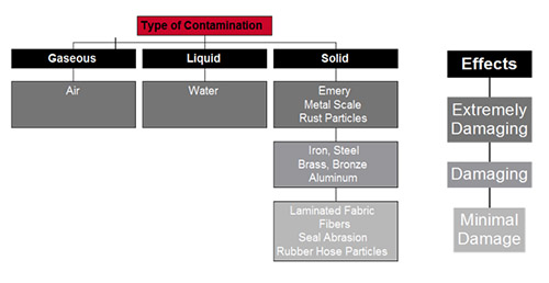
To quantify cleanliness in any fluid power system can’t be condensed into any problem with one solution scenario. Various types of contamination occur in fluid power systems: gaseous (e.g. air), liquid (e.g. water) and solid contaminants (e.g. rust). Solid contamination is subdivided into three groups: extremely hard, hard and soft particles. Extremely hard particles can cause substantial damage in fluid power systems if they are not removed as quickly as possible. Preventive measures can reduce the ingress of contaminants in systems.
Matt Brown, Product Manager Filter Systems, Schroeder Industries, explains that solid particulate cleanliness is expressed in a code. The code expresses a count of particulates, of a particular size in a defined amount of fluid. ISO 4406 code is the most commonly used these days. Other codes in use are NAS 1638 and SAE 4059.
“The objective of the ISO 4406:1999 is to classify particulate contaminants in hydraulic fluids. Particle counts are determined cumulatively, i.e. > 4 μm, > 6 μm and > 14 μm, and coded for easy comparison.,” he said. “Each hydraulic system has an ISO Target Cleanliness Levels (TCL), which is based on the most sensitive system components (small clearances in the micro meter range), system pressure and environmental conditions.”
He recommends that filter manufacturers can be of assistance with general TCL guidance, or also the system manufacturer might have recommendations for the fluid ISO code that should be used.
Water contamination in hydraulic fluids can be expressed in two ways: Parts per million (ppm) or in water saturation in %. The ppm is an absolute value that expresses how much water is present in a particular fluid. If the volume of the fluid is known, the amount of water can be calculated based on the ppm value. “For example: 500 ppm water content in 1000 gallons of fluid equals to 0.5 gallons of water in that fluid. The fluid manufacturer can provide a ppm level for new fluids. This level of water concentration should be maintained during the time of fluid use in a system,” Brown explained.
“The water saturation in percent (%) is measuring the water content relative to the saturation concentration (saturation point). Sensors are available that can measure the water saturation and display, or output the value. A reading of 0% would indicate the absence of water, while a reading of 100% would indicate that a fluid is fully saturated and has free water. Readings between 0 and 100% indicate the amount of dissolved water in the fluid. The fluid’s capacity of taking on water depends mainly on the fluid type and temperature. A fluid is capable to take on more water at higher temperature levels.”
Example: A fluid has 55% water concentration at 70° F. If the temperature is increased to 100° F, the water saturation might drop to 30%. On the other hand, if the temperature is dropped to 40° F, the water saturation might show 100%, with water coming out of solution, resulting in free water in the fluid.
Brown notes that a water saturation sensor is often measuring fluid temperature, as well. “If the fluid saturation curve (ppm value in function of temperature and corresponding water saturation in percent) of a particular fluid is programmed into the sensor, a ppm value could be generated for that particular fluid in the dissolved water range of that fluid.”
“It is also important to note that design issues in the hydraulic system can contribute to air/gases in hydraulic fluids. If the return line is above the fluid level in the tank, free air can be mixed into the fluid. Incorrect motor speeds, unprimed pumps, suction lines too small, suction lifts too high and blocked inlets are among other reasons for air contamination over time. The resting time of the fluid in the tank must be long enough that free air can dissipate from the fluid over time. Fluid that has small, visible air bubbles in the fluid should not be used in hydraulic systems,” he said.
In conclusion, Brown pointed out that an often overlooked source for premature fluid degradation and consequent system damage is heat. “This is especially important if the tanks size is small and the fluid does not have enough time to properly cool down. An elevated heat level in the fluid can speed-up the oil aging effects of the fluid and shorten the overall time the fluid can be used in an hydraulic system. Adding a cooler in the system return, upstream of the hydraulic tank can help in removing excess heat from the fluid.”
By Joyce Laird
Leave a Reply