Contributed by Xing Hong, Founder, WRKR Seal
Hydraulic systems depend on reliable sealing at every connection point. When an O-ring fails in a hydraulic circuit, the consequences range from minor fluid weeping to catastrophic pressure loss, environmental contamination, and unplanned downtime that costs thousands of dollars per hour in heavy industry.
Yet a significant share of hydraulic O-ring failures are preventable. Industry data consistently indicates that incorrect material selection, improper installation, and inadequate groove design account for far more seal failures than normal wear-out. Recognizing how an O-ring failed — and why — is the first step toward eliminating repeat failures.
This article examines the most common O-ring failure modes encountered in hydraulic applications, explains their root causes, and outlines practical prevention strategies.
1. Extrusion and nibbling
What it looks like: The O-ring develops ragged, chewed edges on the low-pressure side. Small fragments of elastomer may break off and contaminate the hydraulic fluid. In severe cases, the entire cross-section thins and distorts toward the extrusion gap.
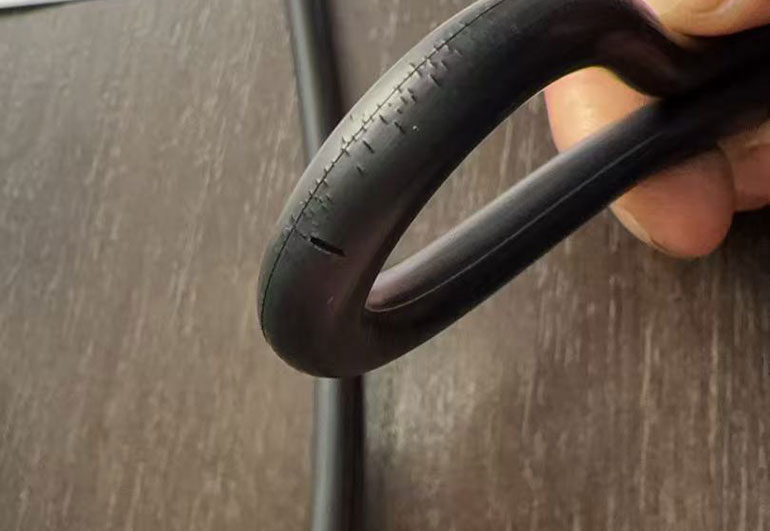
Root cause: System pressure forces the elastomer into the clearance gap between mating surfaces. This occurs when the diametral clearance is too large for the operating pressure, the O-ring compound is too soft, or pressure spikes exceed design limits.
Prevention:
- Tighten machining tolerances to reduce the extrusion gap. For pressures above 10 MPa (1,500 psi), total diametral clearance should generally not exceed 0.10 mm (0.004 in) for a standard 70 Shore A compound.
- Increase material hardness. Moving from 70A to 90A Shore significantly raises the extrusion threshold pressure.
- Install backup rings (anti-extrusion rings) on the low-pressure side. For bidirectional pressure applications, use backup rings on both sides.
- Review system dynamics for pressure transients. Relief valve response lag can allow momentary spikes well above nominal operating pressure.
2. Compression set
What it looks like: The O-ring takes a permanent flat shape conforming to the groove cross-section. It no longer springs back when removed. The seal surface shows a flat contact band rather than a rounded profile.
Root cause: Prolonged compression at elevated temperature causes the elastomer’s polymer chains to permanently rearrange. The seal loses its elastic memory and can no longer maintain contact force against the sealing surface. Thermal cycling accelerates the process — each heat/cool cycle incrementally increases permanent deformation.
Prevention:
- Select compounds with low compression set values at the actual operating temperature. Standard NBR compounds typically exhibit 20-40% compression set at 100 degrees C after 70 hours (per ASTM D395 Method B). FKM compounds perform significantly better at elevated temperatures.
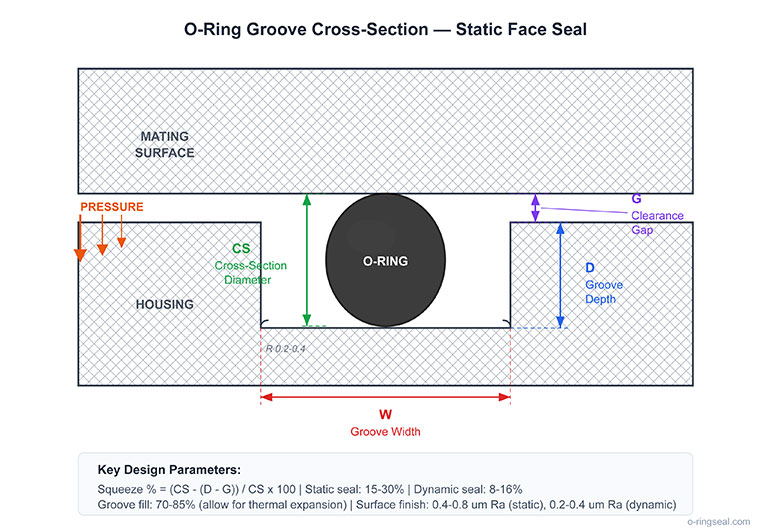
- Ensure proper groove design (o-ringseal.com/resources/groove-design/) with correct squeeze ratio. Under-compression accelerates set because the seal operates closer to its elastic limit from the start.
- Avoid over-compression as well. Squeeze ratios above 30% in static applications, or above 16% in dynamic applications, generate excessive stress that accelerates permanent set.
- For systems with wide temperature swings, consider HNBR or FKM compounds formulated specifically for low compression set.
Chemical degradation (swelling and shrinkage)
What it looks like: A swollen O-ring appears oversized, soft, and spongy. It may extrude from the groove even at low pressure. A shrunken O-ring appears undersized, hard, and brittle, often with visible surface cracks. Both conditions lead to leakage.
Root cause: Chemical incompatibility between the elastomer and the hydraulic fluid, additives, or contaminants. Swelling occurs when the fluid is absorbed into the polymer matrix. Shrinkage occurs when plasticizers or other components are extracted from the compound by the fluid.
Prevention:
- Verify material compatibility with the specific hydraulic fluid in use — not just the fluid type, but the exact formulation including additive packages. A material compatibility reference (o-ringseal.com/materials/) covering common elastomer-fluid combinations can serve as a starting point, but manufacturer-specific data is always more reliable.
- Account for fluid degradation. Hydraulic oil that has oxidized or been contaminated with water can become significantly more aggressive toward elastomers than fresh fluid.
- When switching hydraulic fluids (for example, from mineral oil to biodegradable ester-based fluid), verify that all existing seals are compatible with the new fluid. EPDM seals that perform well with phosphate-ester fluids will fail rapidly in mineral oil.
- Perform immersion testing per ASTM D471 if published compatibility data is unavailable for your specific fluid-material combination.
4. Spiral failure (torsional damage)
What it looks like: The O-ring develops a series of diagonal cuts or a corkscrew-like twisted pattern around its circumference, as if it has been sliced at regular intervals on a helical path.
Root cause: This failure mode is specific to dynamic reciprocating applications. As the piston or rod strokes, the O-ring simultaneously rolls and slides in its groove. If the friction between the O-ring and the moving surface is uneven, sections of the seal twist relative to each other, creating localized stress concentrations that eventually cut through the material.
Prevention:
- Apply proper lubrication before installation and ensure the hydraulic fluid provides adequate lubrication during operation.
- Use O-rings with a cross-section diameter appropriate for the bore size. Larger cross-sections are more resistant to spiral failure because the torsional stiffness increases with the fourth power of the cross-section radius.
- For long-stroke cylinders where spiral failure is persistent, consider switching to X-rings (quad rings), which have a four-lobed cross-section that resists rolling.
- Reduce surface finish roughness on the dynamic sealing surface to 0.2-0.4 micrometers Ra for reciprocating applications.
5. Thermal degradation
What it looks like: The O-ring surface shows radial cracks (heat checking), hardening, and loss of elasticity. The material may appear glossy or develop a hard, varnish-like surface layer. In extreme cases, the elastomer becomes completely rigid and brittle.
Root cause: Operating temperature exceeds the material’s continuous service rating. Unlike chemical attack, thermal degradation affects the entire cross-section uniformly. It is cumulative and irreversible — even brief excursions above the rated temperature contribute to total thermal damage.
Prevention:
- Match material to the actual thermal environment. NBR is limited to approximately 120 degrees C continuous service. For higher temperatures, FKM (rated to approximately 240 degrees C) or FFKM (rated to approximately 320 degrees C) are appropriate.
- Account for adiabatic heating in high-pressure hydraulic systems. Rapid compression of fluid at restrictions and across relief valves can generate localized temperatures significantly above the bulk fluid temperature.
- Consider thermal gradients. The O-ring temperature at a cylinder rod seal may differ substantially from the reservoir temperature, particularly in systems with high duty cycles.
- When selecting materials by temperature, the relevant specification is the O-ring’s dimensional and material standard (o-ringseal.com/as568/), which defines standard sizes and tolerances designed for reliable sealing across operating temperature ranges.
6. Installation damage
What it looks like: The O-ring shows cuts, nicks, or pinched areas immediately after installation — or fails prematurely in service despite correct material and groove design. Damage is typically localized rather than uniform around the circumference.
Root cause: The O-ring was cut during installation by sharp edges, threads, ports, or keyways that it had to pass over. Alternatively, the O-ring was pinched between mating surfaces during assembly. Installation damage is one of the most frequent causes of early seal failure, yet it is entirely preventable.
Prevention:
– Chamfer all leading edges that the O-ring must pass over during assembly. A 15-20 degree chamfer at the bore or rod entry is standard practice.
– Cover threads, splines, and keyways with installation sleeves or tape during assembly.
– Lubricate the O-ring and the mating surfaces with a compatible lubricant before assembly. For NBR and FKM seals in hydraulic applications, the system’s hydraulic fluid typically serves as an adequate assembly lubricant.
– Never stretch an O-ring more than 50% of its inner diameter during installation. If the design requires greater stretch, the O-ring is undersized for the application.
– Use the correct O-ring size. An undersized seal requires excessive stretch during installation and operates with insufficient cross-section compression. An oversized seal bunches in the groove and is prone to pinching. Standard sizing tools based on the AS568 or metric size standards (o-ringseal.com/size-chart/) help identify the correct dimensions.
7. Explosive decompression (gas permeation failure)
What it looks like: The O-ring develops internal blisters, splits, or craters. The surface may appear pockmarked. In severe cases, the seal fractures into multiple pieces.
Root cause: In high-pressure gas or gas-over-oil systems, gas molecules permeate into the elastomer under pressure. When the system depressurizes rapidly, the dissolved gas expands faster than it can diffuse back out, creating internal voids that rupture the material from within. This is particularly common in natural gas, CO2, and nitrogen systems.
Prevention:
- Use compounds specifically formulated for explosive decompression resistance (tested per NORSOK M-710 or ISO 23936-2).
- Control decompression rates. Slower pressure letdown allows dissolved gas to diffuse out without internal rupture.
- Select harder compounds (80-90A) which have lower gas permeability and higher resistance to internal fracture.
- Reduce the O-ring cross-section where design permits. Thinner cross-sections have shorter gas diffusion paths, reducing the severity of rapid decompression events.
Systematic approach to failure analysis
When a hydraulic O-ring fails, resist the urge to simply replace it with the same part. A structured analysis prevents repeat failures:
- Document the failure. Photograph the failed seal in situ before removal. Note the failure location relative to the pressure and motion direction.
- Examine the failure pattern. Compare the physical appearance to the failure modes described above. The damage pattern almost always points to the root cause.
- Review the operating conditions. Check for recent changes in fluid type, operating pressure, temperature, duty cycle, or maintenance procedures.
- Verify the groove dimensions. Measure the actual groove depth, width, and surface finish. Compare against the design specification. Worn or corroded grooves are a common hidden cause of repeat seal failures.
- Select the corrective action. Address the root cause — not just the symptom. Replacing a seal that failed from extrusion with the same durometer compound and the same clearance guarantees a repeat failure.
Conclusion
Most hydraulic O-ring failures fall into a small number of well-understood categories. Extrusion, compression set, chemical attack, spiral failure, thermal degradation, installation damage, and explosive decompression account for the vast majority of field failures.
The common thread is that each mode is preventable through correct material selection, proper groove design, appropriate installation practices, and matching the seal specification to the actual — not assumed — operating conditions. Investing time in root cause analysis when a seal fails is significantly more cost-effective than repeatedly replacing seals on the same failure cycle.
About the author: Xing Hong is the founder of WRKR Seal (o-ringseal.com), a sealing solutions provider specializing in custom O-rings and industrial seals for hydraulic, pneumatic, and chemical processing applications.