• Skip to primary navigation
  • Skip to main content
  • Skip to primary sidebar
  • Skip to footer

Sealing & Contamination Control Tips

Fluid Power Sealing and Contamination Control Information and Resources

  • News
  • Contamination Control
  • Filtration
  • Seals
  • Fluids
  • Design Guides
  • Advertise
  • Subscribe
You are here: Home / Seals / New algorithm optimizes cylinder guidance systems and reduces seal failure

New algorithm optimizes cylinder guidance systems and reduces seal failure

September 15, 2016 By Mary Gannon

Share

A new mathematical algorithm from System Seals removes the guesswork in selecting cylinder guidance systems while also reducing seal failure.

By Kurt Sassmannshausen, System Seals Product Development Manager
system-seals-guide-band-rod-small
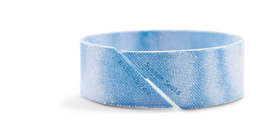
The 847 Series high-strength composite guide band rod is a low-friction guide band made from TC1, a high-compressive strength composite. This guide band is substantially stronger than nylon-based materials and offers considerably lower water absorption. This new composite provides more accurate piston and rod guidance inside the cylinder under widely varying load conditions. Reduced bushing deformation allows the seals and wipers to perform at maximum efficiency, while minimizing the risk of scoring and abrasion.

Failing to properly calculate guide-band loads, rod deflections and the stress and strains distributed across cylinder guidance systems is a leading cause for guide-band fracturing and seal failure. Properly designing a cylinder guidance system is essential for maintaining metal clearances, and preventing overloads and equipment damage.

But accurately measuring guidance loads requires more than just guesswork. In most cases, the load is completely unknown and guide bands are often designed on assumptions. Many seal manufacturers mistakenly presume that stress is evenly distributed across the guide bushing, but a closer inspection reveals something else entirely.

Developing a new guidance model

In a fixed cylinder-end system, the amount of deflection in the guide bands increases as the side load increases. This correlation intensifies off-center driving and rod bending, which in turn, increases the load until an equilibrium can be achieved.
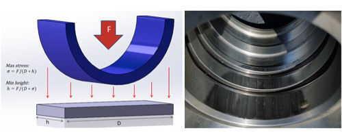
figure-1 System Seals cylinder guidance systems
Figure 1. The use of simplified methods for guide band design can result in significant failures. An example is shown above where a rod crashed into cylinder due to poor guidance design.

To better understand these relationships in a specific cylinder, and to optimize the guidance systems, System Seals in Cleveland has developed a new iterative algorithm that determines the side load, stress and strains distribution across an entire selection of guide bands. An iterative algorithm is a mathematical procedure that generates a sequence of improving solutions for a group of problems with several variables that impact each other.

The key output parameters of this algorithm are stress and strain over the guide bands and the total length of guide band in contact with the rod. These values are necessary to determine the optimum height needed for the guide band.

This is an ideal approach to understand the dynamic behaviors of guide-bands under load. The formula considers tolerances, cylinder weight and the couples created from bearing friction. To confirm the accuracy of the algorithm, Finite Element Analysis models were developed with the same variables and loads. Repeated modeling revealed that a height past which the guide band does not contact the rod provides no support whatsoever.
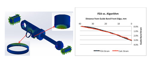
figure-2 system seals
Figure 2. The results of the FEA and calculation models are compared above. As can be seen, the calculation predicts the guide band behavior quite accurately.

Understanding this concept is critical. Adding more guide band to accommodate high loads when the band is already at its optimum length is pointless. But without proper analysis, it is impossible to know if the band height is properly optimized.

Instead of creating a new solid model for each application, as necessary in Finite Element Analysis, the new algorithm pinpoints bearing stress, strain and size solutions based on solving multiple equations simultaneously with only basic dimensional inputs. Because these equations interact with one another, simple algebraic solutions don’t work. A numerical integrator, or iterative method, is required.

Testing conventional wisdom
In one test sample, the guidance of an entire system was located inside the seal groove. In this case two to three 25-mm bands are typically recommended. But the results showed that only 33 mm of the guidance was actually used, based on angular deflections of the system over the guide band. Although the basic calculation suggests that this design would be suitable, it clearly was not.
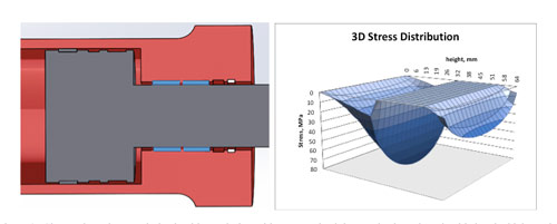
figure-3 System Seals
Figure 3. Shown above is an optimized guidance design with a customized thermoplastic outboard guide band which results in better stress distribution. Note all stress levels remain below yield.

In a second test, a system was examined when a portion of the guidance was shifted outside of the seal groove. There was a 25-mm gap between the inboard and outboard guide bands to allow for a seal groove of 15 mm and 5-mm lands on each side.

The outboard material was a thermoplastic blend with a cross section equal to the main guide band. The test revealed a high load on the outboard guide band that created stresses higher than its yield. But a third test, where the cross section was reduced, the load was distributed to the point where the outboard guide band carried 16 percent of the bearing load, and yielding stopped in all of the guide bands. It was a clear example of a guidance system optimized by position, dimensions and choice of material.

Fixed-cylinder and free-rod end
In another test, systems with fixed cylinder ends and free-rod ends where examined. This included rams, presses and AGC-type cylinders. In this category, a standard 1,050-mm bore with a 960-mm rod AGC cylinder was used for the analysis.
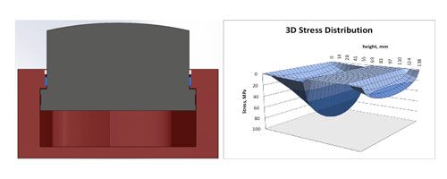
figure-4 System Seals
Figure 4. Optimized AGC guidance design. Note all stress levels remain below yield.

The traditional approach is to install all of the guidance internal to the seals. Here, the analysis showed that about 70-mm of axial contact height occurred on the guide band. This means that only 75 mm is actually needed.

However, the leading edge of the guide band experienced stress values greater than its yield, so adding more guide bands would not have solved the problem. Only 69 mm of bearing height contacted the rod initially. After yielding set in, the bearing deformed to a larger contact area, and this approach would likely have resulted in a variety of failures that could have been avoided with customization.
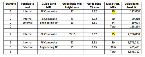
table-1 System Seals
Table 1. Numerical values of calculations

An alternative design is to incorporate a guide band in the outboard position made of an engineered thermoplastic with an optimized cross section and height of 3.65 and 15 mm, respectively. This results in a balanced load distribution, allowing peak stresses in both bearings to remain below the yield values and the outboard guide band to carry about 15% of the load.

Conclusion
Traditional methods for estimating guide band stresses often fall short from misconceptions that loads distribute evenly. However, advanced methods such as Finite Element Analysis require resources that are not always available. Accurately predicting guide band loads is critical in preventing cylinder and seal failures. By using an iterative algorithm, the shortfalls of simplified assumptions can be avoided.

System Seals
www.systemseals.com

Filed Under: Featured, News, Seals Tagged With: systemseals

Primary Sidebar

Fluid Power World Digital Editions

Fluid Power World Digital Edition

Browse the most current issue of Fluid Power World and back issues in an easy to use high quality format. Bookmark, share and interact with the leading design engineering magazine today.

Fluid Power Design Guides

fluid
“sact
EXPAND YOUR KNOWLEDGE AND STAY CONNECTED
Get the latest info on technologies, tools and strategies for Fluid Power Professionals.

Meta

  • Log in
  • Entries feed
  • Comments feed
  • WordPress.org

Archives

  • May 2026
  • April 2026
  • March 2026
  • February 2026
  • January 2026
  • November 2025
  • October 2025
  • September 2025
  • August 2025
  • July 2025
  • June 2025
  • May 2025
  • April 2025
  • March 2025
  • February 2025
  • January 2025
  • December 2024
  • November 2024
  • October 2024
  • September 2024
  • August 2024
  • July 2024
  • June 2024
  • May 2024
  • April 2024
  • March 2024
  • February 2024
  • January 2024
  • December 2023
  • November 2023
  • October 2023
  • September 2023
  • August 2023
  • July 2023
  • June 2023
  • May 2023
  • April 2023
  • March 2023
  • February 2023
  • January 2023
  • December 2022
  • November 2022
  • October 2022
  • September 2022
  • August 2022
  • July 2022
  • June 2022
  • May 2022
  • April 2022
  • March 2022
  • February 2022
  • January 2022
  • December 2021
  • November 2021
  • October 2021
  • September 2021
  • August 2021
  • July 2021
  • June 2021
  • May 2021
  • April 2021
  • March 2021
  • February 2021
  • January 2021
  • December 2020
  • November 2020
  • October 2020
  • September 2020
  • August 2020
  • July 2020
  • June 2020
  • May 2020
  • April 2020
  • March 2020
  • February 2020
  • January 2020
  • December 2019
  • November 2019
  • October 2019
  • September 2019
  • August 2019
  • July 2019
  • June 2019
  • May 2019
  • April 2019
  • March 2019
  • February 2019
  • January 2019
  • December 2018
  • November 2018
  • October 2018
  • September 2018
  • August 2018
  • July 2018
  • June 2018
  • May 2018
  • April 2018
  • March 2018
  • February 2018
  • January 2018
  • December 2017
  • November 2017
  • October 2017
  • September 2017
  • August 2017
  • July 2017
  • June 2017
  • May 2017
  • April 2017
  • March 2017
  • February 2017
  • January 2017
  • December 2016
  • November 2016
  • October 2016
  • September 2016
  • August 2016
  • July 2016
  • June 2016
  • May 2016
  • April 2016
  • March 2016
  • February 2016
  • January 2016
  • December 2015
  • November 2015
  • September 2015
  • August 2015
  • July 2015
  • June 2015

Recent Comments

  • Are clogged hydraulic filters better? | Sealing & Contamination Control Tips on What types of hydraulic filters are available?

Categories

  • Blogs
  • Contamination Control
  • Featured
  • Filtration
  • Fluids
  • Mobile Hydraulic Tips
  • News
  • Products
  • Seals
  • tanks and reservois
  • Testing Equipment
  • Uncategorized

Recent Comments

  • Are clogged hydraulic filters better? | Sealing & Contamination Control Tips on What types of hydraulic filters are available?

Archives

  • May 2026
  • April 2026
  • March 2026
  • February 2026
  • January 2026
  • November 2025
  • October 2025
  • September 2025
  • August 2025
  • July 2025
  • June 2025
  • May 2025
  • April 2025
  • March 2025
  • February 2025
  • January 2025
  • December 2024
  • November 2024
  • October 2024
  • September 2024
  • August 2024
  • July 2024
  • June 2024
  • May 2024
  • April 2024
  • March 2024
  • February 2024
  • January 2024
  • December 2023
  • November 2023
  • October 2023
  • September 2023
  • August 2023
  • July 2023
  • June 2023
  • May 2023
  • April 2023
  • March 2023
  • February 2023
  • January 2023
  • December 2022
  • November 2022
  • October 2022
  • September 2022
  • August 2022
  • July 2022
  • June 2022
  • May 2022
  • April 2022
  • March 2022
  • February 2022
  • January 2022
  • December 2021
  • November 2021
  • October 2021
  • September 2021
  • August 2021
  • July 2021
  • June 2021
  • May 2021
  • April 2021
  • March 2021
  • February 2021
  • January 2021
  • December 2020
  • November 2020
  • October 2020
  • September 2020
  • August 2020
  • July 2020
  • June 2020
  • May 2020
  • April 2020
  • March 2020
  • February 2020
  • January 2020
  • December 2019
  • November 2019
  • October 2019
  • September 2019
  • August 2019
  • July 2019
  • June 2019
  • May 2019
  • April 2019
  • March 2019
  • February 2019
  • January 2019
  • December 2018
  • November 2018
  • October 2018
  • September 2018
  • August 2018
  • July 2018
  • June 2018
  • May 2018
  • April 2018
  • March 2018
  • February 2018
  • January 2018
  • December 2017
  • November 2017
  • October 2017
  • September 2017
  • August 2017
  • July 2017
  • June 2017
  • May 2017
  • April 2017
  • March 2017
  • February 2017
  • January 2017
  • December 2016
  • November 2016
  • October 2016
  • September 2016
  • August 2016
  • July 2016
  • June 2016
  • May 2016
  • April 2016
  • March 2016
  • February 2016
  • January 2016
  • December 2015
  • November 2015
  • September 2015
  • August 2015
  • July 2015
  • June 2015

Categories

  • Blogs
  • Contamination Control
  • Featured
  • Filtration
  • Fluids
  • Mobile Hydraulic Tips
  • News
  • Products
  • Seals
  • tanks and reservois
  • Testing Equipment
  • Uncategorized

Meta

  • Log in
  • Entries feed
  • Comments feed
  • WordPress.org

Footer

Sealing and Contamination Tips

Fluid Power World Digital Network

  • Fluid Power World
  • Mobile Hydraulic Tips
  • Pneumatic Tips
  • Hose Assembly Tips
  • Leadership in Engineering

Sealing & Contamination Control

  • Subscribe to Fluid Power World
  • Videos
  • Advertise with us
  • About us

Copyright © 2026 · WTWH Media, LLC · Privacy Policy