Contamination is widely recognized as the leading cause of premature failure in fluid-power systems. Thus, keeping contaminants in check helps ensure components and systems perform as intended and last a long time, with minimal unscheduled downtime. Heed the following advice for proper fluid power contamination control.
Contamination comes in several forms. Two key culprits are particulates and water, and both are problematic in pneumatic and hydraulic circuits.
Keep dirt out of fluid

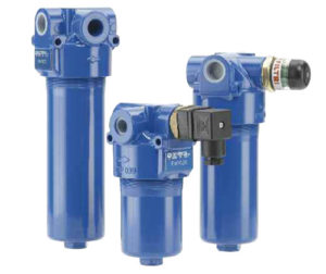
Filtration is essential to prevent damage from solid particles like dust and dirt. Solid particles traveling through a system can score and abrade surfaces, enlarge critical clearances, promote internal leakage and, in hydraulics, even act as a catalyst to chemically break down the fluid. Particulates come from several sources, including built-in debris left over after manufacturing components; by-products of normal internal wear and tear during operation; and dirt ingested from the outside environment. Filters trap such contaminants, but the necessary level of filtration varies with the application and system.
Hydraulic systems have a critical contamination-tolerance level. In essence, it’s the amount and size of dirt particles in the fluid that components can tolerate without harm. Equipment using fluid at that level of cleanliness, or cleaner, tends to run as intended with minimal problems. Exceeding that limit, however, negatively impacts component wear, life and performance. The necessary fluid-cleanliness level is usually based on the most sensitive component in a system. For instance, the recommended fluid cleanliness level for a gear pump is typically less stringent than that for a proportional-control valve.
Most hydraulic manufacturers rate a component’s acceptable operating fluid cleanliness level based on ISO Standard 4406. The standard lists various degrees of fluid cleanliness, determined by measuring the number of particles sized >4, >6 and >14 microns present in a 1 ml fluid sample.
To maintain a specific fluid-cleanliness level, hydraulic filters are available with various beta ratios. The beta ratio is a measure of the filter media’s particle-capture efficiency with standard-size particles. A beta ratio is determined by testing a filter using the ISO 16889 multi-pass method. It evaluates filtration performance by measuring the number of certain-size particles in the fluid upstream and just downstream of the filter. That’s important because if a filter data sheet simply provides an efficiency number, without noting the size of particles the filter captures, the efficiency number is completely arbitrary.
Beta ratios are important to help identify the quality of a hydraulic filter element. If using ISO 4406 levels to help identify and specify recommended oil cleanliness, then filter efficiency ratings let users meet that target by knowing how well a given filter media can trap and retain particle contamination.
Clean, safe air

In pneumatic systems, compressed-air filters are generally rated for the minimum particle size that their elements will trap. Most industrial applications work fine with filters that remove particles 40 to 60 microns in size and greater. But some devices demand cleaner air and require, for example 5 micron filters, often installed at a specific point of use. However, note that finer ratings tend to increase the pressure drop through the filter, which raises operating costs. Many filter manufacturers define particle-removal size, flow rating, pressure loss and dirt-holding capacity of specific products.
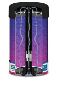
In critical applications requiring extremely clean air, coalescing filters are recommended. These have several layers of specialized media that coalesce and collect more than 99% of oil and water aerosols, and remove particles as small as 0.01 micron. However, coalescing filters create a greater restriction to flow and higher pressure losses, compared to standard air filters. Users typically install a standard filter just upstream as a prefilter to extend the life of the coalescing unit.
Proper selection and installation
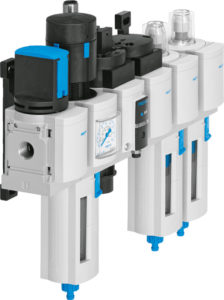
Hydraulic filters can be installed in pressure, return and, sometimes, in suction lines, depending on the application, circuit design and degree of protection needed. In pneumatic systems, a number of filters are usually mounted throughout a circuit to protect individual machines and processes. They’re often installed in conjunction with regulators and sometimes lubricators, comprising an FRL.
Keep in mind that contamination that is damaging in one system may be harmless in another. In general, select the level of filtration that’s appropriate for the application. Running systems cleaner than necessary does no harm to a system, but it wastes money.
Also specify the right filter size. Select a filter for minimal pressure drop at the highest flow. Most manufacturers supply pressure and flow curves to rate pressure drop and dirt-holding capacity. Undersized filters hurt energy efficiency. Typically, while larger filters are more expensive up front, they produce lower pressure losses, provide longer operating life and cost less in the long run.

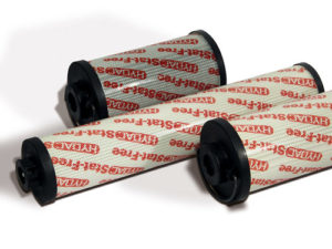
Also consider quality—all filters are not made the same. For instance, they routinely come with elements made of glass, cellulose or other fibers in various constructions. Efficiency, dirt-holding capacity and pressure drop can vary by design, media and manufacturer, even among units with the same micron or beta rating.
Finally, experts strongly recommend that users change the filter element when necessary. As a filter traps contaminants it eventually reaches its dirt-holding capacity. That increases pressure drop, wastes energy and may pass contamination downstream—totally negating the benefits of installing a filter in the first place. All filters should be fitted with pressure-differential gauges or sensors to signal when a filter needs replacement.
Dry systems work best
Water is also a damaging contaminant in fluid power systems. Water vapor in the air is routinely drawn into compressors that raise the air’s pressure, temperature and dew point increase. Any subsequent cooling downstream can cause the water vapor to condense and liquefy. Likewise, humid air can pass into hydraulic systems through reservoir breathers, and liquid water can enter through imperfect seals. It can even get into systems via new oil, such as from drums of hydraulic fluid stored outdoors.

Water can change the physical characteristics of hydraulic fluid—for instance, lowering viscosity and load-bearing capacity—and chemically react to cause corrosion or form harmful sludge. That can make components malfunction and shorten the life of the hydraulic fluid itself.
Mass-transfer and flash-distillation vacuum dehydrators are two types of devices that remove free and dissolved water. Likewise, water-absorbing hydraulic filters have specially designed media that trap damaging water, as well as solid contaminants like dirt and rust. And devices like desiccant breathers mounted on reservoirs help keep water out of the circuit in the first place.
In pneumatic circuits, liquid water in pneumatic systems creates problems like corrosion and bacteria growth, which in turn leads to unresponsive controls or component breakdowns. Several types of dryers are available using refrigeration, heated and heatless desiccant, or membrane technology. These units lower pressure dew points of compressed air and eliminate liquid water from a circuit.

Leave a Reply