By Josh Cosford, Contributing Editor
The use of hydraulic symbols must be comprehensive in your efforts to detail the workings of a complete hydraulic system. Hydraulic machines consist of more than pumps, valves and actuators, of course, even though they are often the stars of the show. Those stars would quickly fall into the other side of fame without components to condition and monitor your machine.
Conditioning symbols are those representing components used to filter, heat, cool or otherwise treat the hydraulic fluid of your machine. If you recall from way back in Hydraulic Symbology 101, we draw fluid conditioning symbols most often with a diamond-shaped basic shape. From this basic diamond, fluid moves through the component symbol in many ways, I’ve detailed the basic filter symbol, shown in Figure 1.
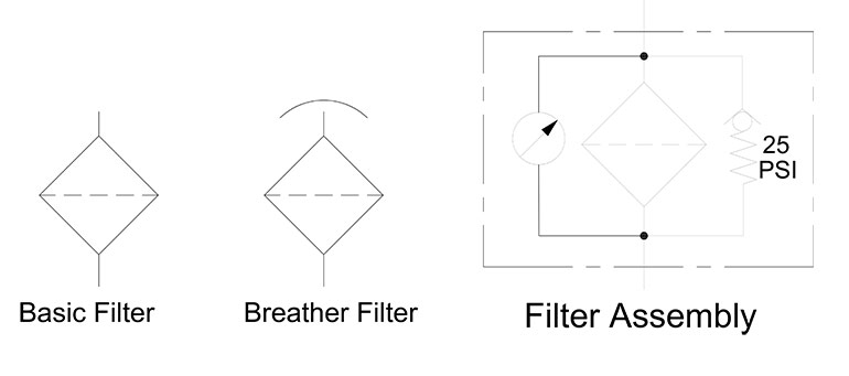
Imagine hydraulic fluid flowing in from the top of the diamond, where it’s able to fill the chamber. The dashed line is neither a pilot or drain line, as is described in previous articles, but perforations. Fluid must pass through the perforations leaving particles trapped atop the layer. Actual perforations are microscopic, but it represents the real-world filter quite well. Clean fluid exits the bottom, most often directly into the reservoir, once again ready to be pumped out.
Want more symbology content? Download our 45-page Symbology Building Blocks e-book now.
Hydraulic systems need protection from atmospherically suspended particles such as dust, welding fallout and machining particles. Differential cylinders require an extra fluid volume to extend, and that fluid must draw from the reservoir. As the fluid volume decreases in the reservoir, air draws in to replace it, and without some form of contamination removal, atmospheric contamination may enter the system. The breather filter allows air to pass while trapping particles. The second symbol in Figure 1, with the arc above the filter element, is such a device.
The complete filter assembly in Figure 1 is a compilation of components for filtering and monitoring filter condition. Fluid passes straight through the middle, where particles get trapped inside the media. The symbol for a pressure gauge sits to the left. This pressure gauge differs in that two opposed lines terminate on either side of the gauge. Known as the differential pressure gauge, it compares pressure upstream to downstream of the filter to show the pressure drop through the filter element. Showing pressure drop rather than absolute pressure offers an accurate method to trigger filter replacement when the filter begins to clog. An upstream pressure gauge would provide just a backpressure reading at the filter, instead of pressure drop through the element.
To the right of the filter is a spring offset check valve denoted with a 25 psi spring value. This check valve provides a bypass flow path should pressure drop increase due to an excessively clogged filter. Return lines are generally poor locations for backpressure, so this check valve provides an alternate flow path when the filter becomes too clogged to flow well enough. At 25 psi, the check valve starts to open to reduce backpressure through the element. Take note that flow through the check valve is not filtered, allowing contamination to pass right through.
In Figure 2, I show the compound symbol for a duplex filter assembly. A duplex filter allows on-demand filter change while the hydraulic system still runs. The fluid first enters from the top of a 3-way ball valve. The three cones show the top inlet and two horizontal outlets possible depending on the location of the handle shown sprouting from the bottom. Some 3-way valves are simply a circle with an L-shaped line connecting two of the three ports, but I find this version more succinct.
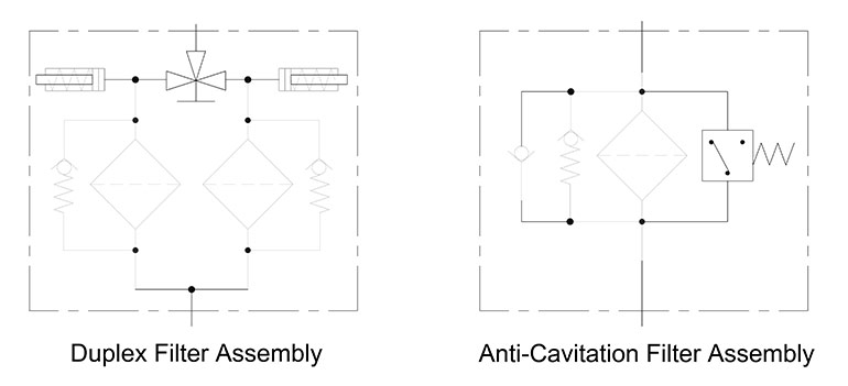
Juxtaposed to the 3-way ball valve are two objects appearing to be spring return cylinders. These are, in fact, pop-up indicators. The spring value would be equivalent to about two-thirds the setting of the bypass check valves. If the bypass valves begin to open at 45 psi, the pop-up indicator overcomes its spring at 30 psi to warn the maintenance team that the filter should be changed soon. Often turning from green to red at the time of pop-up, they automatically reset when pressure drop returns to normal after the filter change.
You can see each filter has its bypass valve (which is sometimes in the filter element itself), although I’ve omitted the spring valve to reduce clutter. After fluid passes the filter through the bottom, both elements join to a single outlet where clean oil exits the assembly. Most duplex filters are inline mounted rather than in-tank and may be pressure filters as well as return line filters.
The anti-cavitation filter assembly in Figure 2 provides a couple more symbology options for a filter assembly. Much of it is the same as the filter assembly in Figure 1 but includes two more options. The second check valve is to allow an anti-cavitation function to the system. There are circumstances where a hydraulic system might want to “float,” meaning that it could be pulled, lifted or pushed under gravity or load forces. For example, if a cylinder is pushed upon while stationary, fluid may need to be pulled in from the reservoir to take up the volume differential. Without the check valve, the cylinder could cavitate and create air bubbles to potentially damage the cylinder when re-pressurized.
The component to the right of the diamond filter is a differential pressure switch. By comparing pressure upstream to downstream as in the pressure gauge of Figure 1, this switch triggers some light, PLC or another warning that the filter should be changed soon. The symbol itself is a square box with a fixed spring symbol atop. The three dots are electrical contacts, while the line shows the default electrical path in this case “closed” to connect the bottom to the left side contact. When pressure matches the switch’s spring value, the contact shifts to the right, closing the electrical circuit and signalling the warning.
No fluid conditioning package is complete without control over the temperature of the hydraulic fluid. Heaters, coolers or heat exchangers benefit most hydraulic systems, especially those located variable climates or working conditions. Figure 3 shows the diamond symbol as heaters and coolers. The first symbol on the left depicts the vertical hydraulic fluid flow path, bisecting two inward-facing arrows. These arrows do not denote a fluid flow path, as is typical for the symbol, but the direction of thermal transfer, and showing the symbol for a heater, such as an electric in-tank coil type.
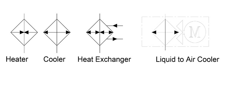
The cooler symbol second left is very similar to the heater save the two outward-facing arrows, which represent heat evacuating from the fluid. This symbol is basic and does not tell us if the cooler is liquid-to-liquid or liquid-to-air, although I would assume liquid-to-air if compared to the symbol on its right. The heat exchanger symbol combines the internals of the heater and cooler, showing the capacity to direct heat inward or outward (but never simultaneously). However, poking out from the right is an extra pair of fluid lines first entering from the top and then exiting from the bottom. The extra lines stand for a coolant fluid, which may be city water or water-glycol, either cooled or heated. Tube and shell or brazed plate cooler are examples of a liquid-to-liquid cooler.
The final compound symbol surrounded by an enclosure line is the liquid-to-air cooler. This unit would be either a tube and fin or bar and plate style cooler common to forced air coolers. The compound shape to the right shows two conjoined triangles forming the fins of a cooling fan attached to the circular prime mover symbol for an electric motor. The letter “M” stands for motor, and if its enclosure were square would signal an internal combustion engine.