
By Josh Cosford, Contributing Editor
Out of any topic under the patio-sized umbrella of fluid power, hydraulic symbology garners the most requests from those wishing to learn more about fluid power. Reading any schematic with more than three symbols can be daunting if your experience is limited. But it’s not impossible to learn. In fact, it only takes a basic level understanding of how symbols work and how they’re arranged in a diagram. One challenge – even if you’ve memorized every symbol in the library – is understanding why a particular symbol is used in a circuit; that part is hard to teach and just comes with experience.
 This month, I will give you the basics so you know how the standardized lines and shapes are drawn and structured to be universally interpreted. If you’re already familiar with schematics, please bear with the simplicity. In some cases, I’m also going to try to give examples of older symbols, since many plants have old machines with old schematics.
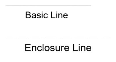
The basic elements of any schematic are the lines of various types. The most commonly used line is the solid, black style, which I call the Basic Line. This is a multi-function line, and is used for all the common shapes (such as squares, circles and diamonds) in addition to representing fluid conductors, such as suction, pressure and return lines.
Want more symbology content? Download our 45-page Symbology Building Blocks e-book now.
 Another style of line commonly used is the dash-dot Boundary or Enclosure Line. This represents a grouping of hydraulic components as part of a compound component (such as a pilot operated directional valve, with both pilot and main stage valve together), a sub circuit (such as a safety circuit for a hydraulic press) or a stand-alone hydraulic manifold with cartridge valves. Generally, the Boundary Enclosure is a four sided polygon, using the dot-dash line, with various valve symbols contained within as representation of the actual hydraulic system.
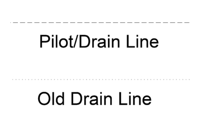
The third most common line you will see is the simple dashed line. This is a dual function line, representing both pilot and drain lines. A pilot line in both representation and function uses hydraulic energy to signal or operate other valves. Learning to comprehend pilot lines is key to understanding advance hydraulic schematics. As a drain line, the dashed line simply represents any component with leakage fluid needing a path represented in the drawing.
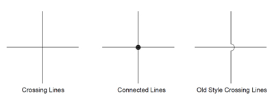 When lines in a schematic represent hoses, tubes or pipes on a machine, they are often required to cross or join with other conduits. In the case of joined hydraulic conduits, a dot or node is added to the joint on the drawing to show how they’re joined on the machine. A line that crosses on a drawing doesn’t necessarily have to cross on the machine, but clarification on the drawing is required to differentiate lines that cross from lines that join. Crossing lines used to be shown as a jump or bridge, but the current standard is now that they simply cross with no drama.
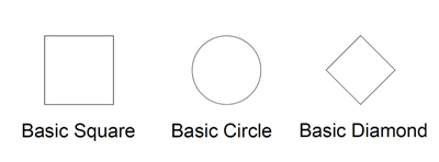
If we get slightly more advanced than your basic line, we have three other common shapes used in hydraulic schematics. These are the circle, square and diamond. Ninety nine percent of hydraulic symbols use one of these three as a foundation. Pumps and motors of every kind are drawn using a circle, as are measuring instruments. Valves of every kind use the basic square as a start. Some are simply one square, such as pressure valves, but others use three joined squares, such as with a three-position valve. Diamonds are used to represent fluid conditioning devices, like filters and heat exchangers.
 A square is used mostly for valves of various kinds; pressure valves and directional valves are the most common use. A single square is used for every simplified pressure valve I can think of; relief valves, pressure reducing valves, counterbalance valves, sequence valves etc. Every pressure valve, with the exception of the reducing valve, is what we call normally closed, which does not pass fluid in its neutral state. The valves must be open via direct or pilot pressure, which can occur anywhere within the limits of its spring setting.
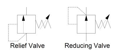 If we break down the relief valve symbol, we can see a few more shapes not previously discussed. The first is the arrow. In most cases arrows are not used, and we assume fluid can flow in either direction. In the case of our relief valve, fluid flows only one way through it, as we can see by the vertical, offset arrow. The second arrow of the relief valve is drawn diagonally, which signifies adjustability. In this case, the spring it’s overlaying means this relief valve has a spring with adjustable pressure settings.
Let’s assume the relief valve is set to 2,000 psi. You’ll have noticed the dashed line coming from the bottom of the symbol, rounding the corner and is attached to the left side. This dashed line indicates the valve is directly operated by the pressure at its inlet port, and that pilot fluid can affect the valve by pushing the arrow to the right. The actual valve has no arrow, of course, but as is the nature of hydraulic symbols, just represents a visual model of what occurs. As pressure in the pilot line approaches 2,000 psi, the arrow is pushed until the valve reaches the centre, allowing fluid to pass, which in turn reduces pressure until upstream is 2,000 psi.
The pressure reducing valve is the only normally open pressure valve in hydraulics. As you can see, it’s very similar to the relief valve, save two changes in the symbol. Firstly, the arrow shows it flows in its neutral position, whereas the relief valve is blocked. Secondly, it gets its pilot signal from downstream of the valve. When downstream pressure rises above the spring setting value, the valve closes, preventing incoming pressure from reaching the downstream path, which allows pressure to decay back to below the pressure setting.
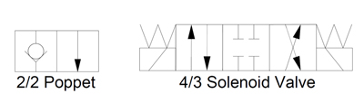 Directional valves continue to use the square envelopes, as is seen by the 2/2 poppet valve and 4/3 solenoid valves shown. Each envelope—or square—represents one of the possible positions of the valve. The 2/2 poppet doesn’t specify how the valve shifts, but that it will block flow in one position, and allows flow in the other. The 4/3 valve shows that it blocks all flow in the middle (neutral) position. It can then be shifted to the left or right envelope, essentially reverse the flow out the work ports. The spring symbols are located above each of the solenoid symbols, and this represents dual solenoids with spring centered function.
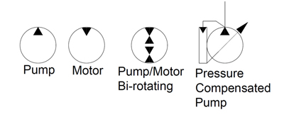 Circles represent pumps and motors in 90% of the symbols used, and can also be used in check valves or pressure gauges. The triangular arrows represent the direction fluid takes; in the case of pumps, it faces outward, and with motors, it faces inward. Motors are often bi-rotational, and will have a triangle at the bottom as well, permitting fluid to enter at either port. Some pumps can also be motors at the same time, and further still, can be bi-rotational, as is shown in the next symbol. The pressure compensated, variable displacement pump symbol varies widely, and sometimes is just shown with an arrow inside the circle. This particular example is my favourite, and is somewhat simple, although they can get quite complex, showing individual symbols for various compensators, orifices and/or electro-proportional valves.
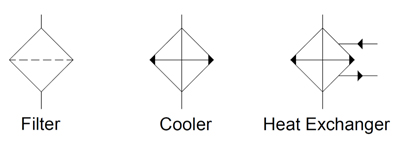 The last basic shape commonly used in hydraulic symbology is the diamond. Diamonds represent conditioning devices, such as filters, heaters or coolers. You can imagine the dashed line bisecting the filter symbol acts to trap particles as they pass through. For the cooler, the two outward arrows represent the heat radiating from the cooler. Finally, the heat exchanger shown is the liquid-to-liquid type, showing the path of incoming and outgoing fluid that removes heat from the system.
The basics of hydraulic symbology are quite easy, but I’ve only scratched the surface. There are many specialized symbols representing things like electronics, accumulators, various cylinders and ball valves, which I don’t have the room to show. Furthermore, each symbol I’ve shown represents a small portion of the modifications possible to each; there is probably a hundred or more ways to represent a hydraulic pump with a schematic symbol.
Finally, the way in which hydraulic symbols are combined to create a complete schematic representing an actual machine is endless. I recommend you spend time reading hydraulic schematics to interpret the symbols, whenever you have time. Not only will you discover unique symbols, but you’ll come across unique ways to use old symbols and components in a hydraulic circuit.