
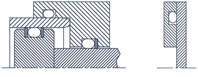
 Backup rings are used for both static and dynamic fluid power applications and prevent the migration or extrusion of an O-ring in the gap as pressurization and de-pressurization/pressure cycling occur. The profile shape of the backup rings is usually rectangular but may also be concave at the face mating with the O-ring. Manufactured in various PTFE compounds, backup rings may be continuous, slotted or spiralled.
The continuous STE design is predominantly used for internal, radial-static and dynamic applications.
The slotted STG design is for external sealing, radial-static and reciprocating applications.
The spiralled STS design can be used for both external sealing and internal sealing applications. Compared with the other two designs, this form offers the advantage that, in service conditions involving high temperature fluctuations, the ring is able to compensate for larger tolerance changes without problem through spiral contraction or extension.
Type ST… backup rings are manufactured as standard from unfilled PTFE. This material is ideally suited to light to medium-duty applications. In the case of heavier-duty requirements, the PTFE material must be filled. As a rule, the filler material takes the form of fibreglass, although the PTFE may also be reinforced by bronze or carbon.
The STE continuous and STG slotted designs can also be manufactured in other materials such as PU, POM, PA etc. where necessary.
The STM types for metric size ranges and STI designs for inch sizes are manufactured from a special polyester elastomer in the injection moulding process. Owing to its high resilience, this material offers the advantage that it can also be used for external sealing in continuous grooves. These backup rings are likewise available in polyurethane. Simple snap-fitting and automatic installation are likewise possible with the above-mentioned materials. Selection of the appropriate material combinations also ensures that these backup rings exhibit a high level of extrusion resistance.
Benefits include:
• Wide range of different materials
• Very good thermal and chemical resistance
• Individual size ranges possible
• Simple groove design
• Capability to bridge large seal gaps
• Easy to fit
Technical data:
Velocity: reciprocating / rotating up to approx. 2 m/s (depending on material)
Temperature: – 60° C to + 200° C (depending on material selection)
Pressure: up to 200 MPa (2000 bar) static load (depending on material selection)
up to 40 MPa (400 bar) dynamic load (depending on material selection)
up to 15 MPa (150 bar) rotating load (depending on material selection)
It is recommended to provide backup rings where relatively high pressures in excess of approx. 5 MPa (50 bar) are involved, and particularly where relatively large gap dimensions need to be bridged between the components requiring sealing. A backup ring is also advisable in applications involving high velocities and frequencies, heavy pulsation, elevated temperatures and, in particular, temperature fluctuations.
In single-acting applications where pressurisation only takes place on one side, it is usually sufficient to install one backup ring on the non-pressurised side. If reciprocating pressurisation is expected, two backup rings will need to be used, one on either side of the O-ring.
The use of backup rings enables the specified gap dimensions to be somewhat enlarged, although the clearance fit H8/f7 is recommended in order to ensure functional reliability.
The recommendations relating to the groove dimensions and surface finish, i.e. roughness, tolerances, insertion bevels etc. are essentially the same as those applicable to O-rings.
S.F. Components
www.sf-components.com
Leave a Reply