
Automatic particle counting is a key to keeping track of fluid cleanliness in within a hydraulic system. Dan Zoller, Group Product Manager Filter Systems at Schroeder Industries says that a common practice has been to take oil samples from the system and have them sent to a lab for analysis, or evaluated on site by hand (e.g. Patch test with Microscope), to determine the particulate contamination levels (e.g. ISO Code). Using this method means that determining the fluid cleanliness information can take several days, maybe even up to a several weeks for the results to be known. This makes it difficult, or even impossible, to react to changing conditions in a hydraulic system.
“The development and implementation of contamination sensors allows for immediate measurement of the fluid contamination and the presentation of a value representing that cleanliness level (e.g. ISO Code).” Zoller said. “The process of particle detection, particle counting and particle grouping to determine the corresponding cleanliness codes can now be automated and does not require any handling by the user.”
He adds that this automated process has several advantages: Sample taking time dramatically reduced, possibility for continued fluid cleanliness monitoring, reduction of outside influences (e.g. dirt from surroundings), a higher degree of repeatable readings (e.g. less influence of user), and possibility to set benchmark levels for decision making (e.g. warning signal or stopping of process).
“Contamination Sensors can principally applied in two ways: In-line—placed in a hydraulic system at strategic place to measure contamination, or used portable/off-line—for sample taking at different places in a system, or at different systems, equipment or places.
In-line contamination sensors
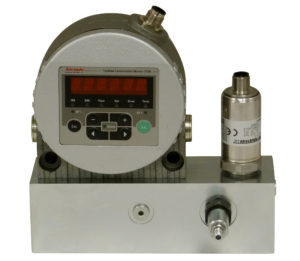
Zoller explains that a contamination sensor measures the particular contamination of fluids by taking a sample out of the main stream and measuring the particulate size, the particulate count in the individual size class and the fluid flow to determine the corresponding cleanliness level (e.g. ISO Code).
“In general, the in-line sensors are optical sensors, where the fluid passes through a light barrier. The light source is either an Infrared LED or a laser. A shadow is created on the photodiode if a particle comes between the light source and the photo detector. This shadow causes the electric signal emitted by the sensor to change. This change can be used to determine the size of the shadow cast by this particle and thus the particle size to be determined. This procedure enables the calculation of the corresponding cleanliness classes. The sensor signals can be made available to PLCs, or monitoring systems, and can be used to control system functions such as if system shut down if benchmark cleanliness levels are exceeded.”
Portable/off-line contamination sensors
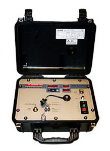
Portable Contamination Sensors use the same technology as in-line sensors. They are available as portable in-line sensors without a pump-motor-group for easy movement between different measuring points. But mostly, they are equipped with integrated pump for bottle sampling, with hoses and test point connections for quick sample taking from fluid reservoirs, control circuits, or high pressure circuits. The tests results are displayed or stored inside the unit and can be downloaded to a PC or onto a USB drive for archiving or processing.
“In addition to the optical sensors technology, Mesh Blockage technology is also used for portable units,” Zoller said. “The Mesh Blockage technology uses fluid flowing through a mesh/screen where the particulates are covering the openings over time. The corresponding increase in differential pressure over time is measured and a cleanliness level is computed.”
Debris sensors
Contamination sensors are placed in a system to take a representative sample out of the fluid flow to measure the contamination levels. This covers the smaller particle sizes that are present in a fluid (e.g. in ISO Codes particle counts are determined cumulatively, i.e. > 4 μm, > 6 μm and > 14 μm, and coded for easy comparison). Larger particulates are included in the code as well but the focus is generally on the fluid cleanliness which is expressed by the smaller particulate sizes.
“The existents of larger particulates (e.g. 70 Microns and larger), especially the sudden increase can give vital information about the health of a hydraulic system or components, levels of wear-and-tear and information for predictive maintenance,” Zoller said.
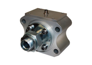
“A debris sensor, unlike a contamination sensor which takes a sample from the main fluid stream, is a full-flow sensor that measures the entire fluid. The particles are determined according to the inductive measurement process, in which a coil system is the key element of the sensor. Metallic particles such as ferromagnetic and non-ferromagnetic are detected and counted individually.”
Many solutions
Determining the fluid cleanliness information no longer needs to be difficult. The latest in both inline and offline/portable particle counting/analysis technology is simplifying the ability to react to changing conditions in any hydraulic system. “Today, it is only a choice of what to use for your specific system/application,” Zoller said.
–Joyce Laird
Leave a Reply